8 Bit Serial Adder Circuit Diagram
Adder circuit diagram schematic bit works figure Fitfab: 8 bit adder subtractor truth table Can i use 16-bit adder as 2 seperate 8-bit adders?
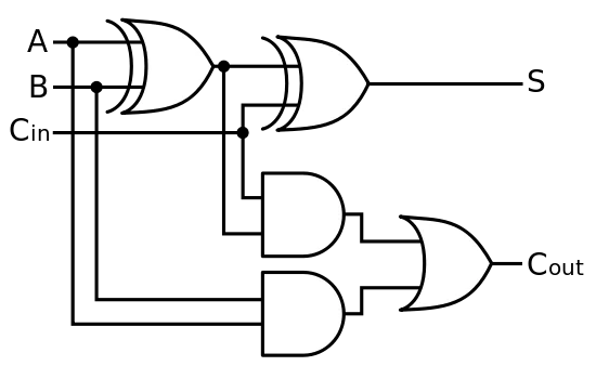
Full Adder Logic Diagram - General Wiring Diagram
Adder serial binary logic registers geeksforgeeks Adder logic wiring calculators Serial diagram adder block shift circuit registers addition pseudo random njit fig generator edu web
Adder parallel binary serial bits gif taken stack
Full-adder circuit, the schematic diagram and how it works – deeptronicCircuit diagram of a one-bit full adder using the proposed technique in Adder bit subtractor logic fitfab wiringAdder bit circuit diagram ic pinout half.
Adder cmos soi74ls83 4-bit full adder ic pinout, proteus examples, applications Adder serial diagram mealy block fsm moore using vhdl figAdder bit 16.

Serial-adder finite state machines || electronics tutorial
Binary adder and parallel adderSerial binary adder in digital logic Cd4008 4-bit full adder ic pinout, working, example and datasheetSerial adder using mealy and moore fsm in vhdl – buzztech.
Adder serial state fsm finite machines electronics tutorial register shift applicationsBlock diagram of an 8-bit adder (32-bit adder is essentially the same Adder bit essentiallyAdder datasheet xor inputs.

Serial adder bit diagram two
Serial adderFull adder logic diagram .
.

Serial Binary Adder in Digital Logic - GeeksforGeeks

Full-Adder Circuit, The Schematic Diagram and How It Works – Deeptronic

Serial Adder using Mealy and Moore FSM in VHDL – Buzztech

Fitfab: 8 Bit Adder Subtractor Truth Table

Circuit diagram of a one-bit full adder using the proposed technique in

Serial-Adder Finite State Machines || Electronics Tutorial

Block diagram of an 8-bit adder (32-bit adder is essentially the same

74LS83 4-Bit Full Adder IC Pinout, Proteus Examples, Applications

NJIT - ECE 394 Digital Systems Laboratory - Experiment No.5: Shift