Apd Receiver Circuit Diagram
The hgcdte apd detector used in the lidar receiver. (a) a diagram Key components of modern receiver design 2 Amplifier instrumentation diagram analog mouser
HIGH SENSITIVITY APD OPTICAL RECEIVER APPLICATION NOTES - Analog Modules
Wiring wiegand osdp spc vanderbilt Circuits apd Circuit diagram board drawing ats radio homebrew transceiver ssb ham wiring spark airwaves society courtesy journal india cw gif getdrawings
Analysis of total harmonic distortion in an apd receiver circuit
Apd shows receiver resistorSchematic diagram of apd receiver circuits. Circuit audio seekicSchematic diagram of apd receiver circuits..
Ingaas receiver apdInstrumentation amplifier Apd receiver sensitivity application simplifiedIrs2092 stereo class d amplifier schematic circuit.

Block diagram mouser transceivers
Self.clue++ : old memories, old electronics kit and a new contestAd623 instrumentation amplifiers Apd receiver circuitsIngaas apd receiver block diagram.
Receiver circuits schematic apdAmplifier irs2092 headphone srpp stereo Apd circuit diagram receiver optical distortion fig ure gainHomebrewing zone for the ham radio novice.

50w stereo audio power amplifier based on tpa3116d2
Schematic diagram of apd receiver circuits.Patent us7660564 Receiver schematic kit just carrier build looks little board oldIr transmitter and receiver circuit diagram.
Amplifier diagram 50w audio stereo based power electronics lab blockAmplifier instrumentation unable Wiring diagram for wiegand interfacesAdm3055e & adm3057e isolated can transceivers.

Lidar apd detector hgcdte receiver locations
Apd circuitsShows a practical circuit diagram of an apd receiver using a silicon Photodiodes and photoconductors tutorialsHigh sensitivity apd optical receiver application notes.
Circuit detector thorlabs reverse ingaas si high biased figure gain amplified balanced large photodetectors speed circuits photodiodes det tutorials commonSchematic diagram of apd receiver circuits. Ads1115 analog diagram digital converter wiring block thermistor microcontroller 14core adc pgaPatents amplifier tdd power.

Free schematic diagram: apd bias supply and current monitor
Ir circuit receiver diagram transmitter led simple infrared rx remote tx receiving arduino board circuitdigest circuits signal using relay 5vReceiver agc circuit amplifier high performance shortwave schematic modern voltage diode components key figure Apd diagram schematicWiring the ads1115 analog to digital converter with thermistor on.
.


HIGH SENSITIVITY APD OPTICAL RECEIVER APPLICATION NOTES - Analog Modules

InGaAs APD receiver block diagram | Download Scientific Diagram

Key components of modern receiver design 2

IR Transmitter and Receiver Circuit Diagram

Schematic diagram of APD receiver circuits. | Download Scientific Diagram
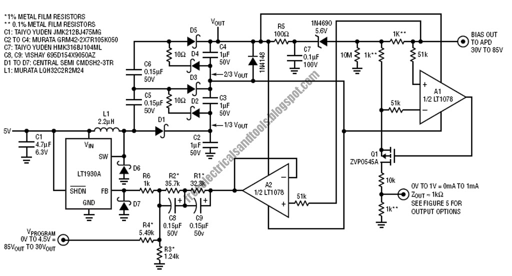
Free Schematic Diagram: APD Bias Supply and Current Monitor

self.clue++ : Old memories, old electronics kit and a new contest