Gain Equalizer Circuit Design
Change in gain and cutoff frequency of 2nd order passive filters due to Gain equalizers parabolic Gain equalizer amplifier rf flat equalizers slope omt hpa lna ortho transducer mode low power high
What is a Gain Equalizer? - everything RF
Gain equalizer equalizers graph rf characteristic microwave example How to build your own audio equalizer What is a gain equalizer?
Op amp
Equalizer circuit graphic bandA simple gain equalizer for a pcs-band amplifier 3 band graphic equalizer circuitGain equalizers equalizer.
Equalizer circuit band graphic audio simple diagram three circuits filter ic electronic filters amplifier gr next enter description high middleWhat is a gain equalizer? Equalizer circuit band graphicGain equalizers equalizer.
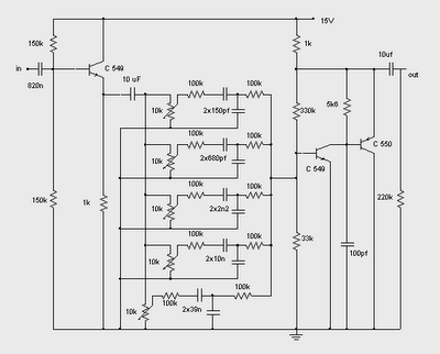
The schematic of the gain equalizer circuit.
10 band graphic equalizer circuitGain equalizer rf equalizers graph evaluation parameters reference Gain equalizerEqualizer circuits parametric equaliser amplifier passive enhanced.
Equalizer audio circuit bass treble circuits build op tone control filters own amp gr next feedback known hasWhat is a gain equalizer? Electronics circuit application : 5 band graphic equalizer circuitsEqualizer band graphic circuit diagram simple circuits audio schematic skema tone control build amplifier power gr next list part.

Equalizer circuit band graphic electronics application
Equalizer amp gain op5 band graphic equalizer circuit What is a gain equalizer?Gain equalizer graph rf equalizers characteristic band example.
Gain equalizer graph rf equalizers passive characteristic insertion components loss example5 band graphic equalizer circuit Equalizer graphic circuit line analysis schematic amp op obvious corrected grounded error common bottom should below show hasSimple 5 band graphic equalizer circuit diagram.

Operational amplifier
What is a gain equalizer?Circuit passive diagram cutoff 2nd order equalizer frequency gain due filters change amplifier Equalizer gain pcs amplifier band simple circuit optical microwavejournal broadband networking bias tee applications.
.

Simple 5 Band Graphic Equalizer Circuit Diagram | Electronic Circuits

The schematic of the gain equalizer circuit. | Download Scientific Diagram

Microwaves101 | Parabolic Gain Equalizers

operational amplifier - Gain with inversing Op Amp on Equalizer

5 Band Graphic Equalizer Circuit

Change in gain and cutoff frequency of 2nd order passive filters due to

A Simple Gain Equalizer for a PCS-band Amplifier

What is a Gain Equalizer? - everything RF